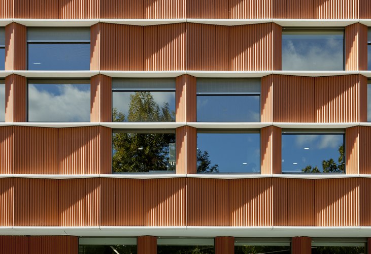
In ventilated facade architecture, the continuous air gap between the outer cladding panel and the insulation layer is the engine of the building’s thermodynamic efficiency. By harnessing natural buoyancy—the stack effect—this cavity evacuates solar heat in summer and keeps structural walls permanently dry year-round.
However, in the event of an active building fire, that same ventilation gap creates a significant safety risk. Left uncompartmentalized, an open air cavity acts as a high-draft chimney, pulling fresh oxygen from base vents and drawing flames, superheated gases, and smoke upwards across multiple floor levels within seconds.
To prevent catastrophic vertical fire spread, facade engineers rely on passive fire protection systems designed to maintain daily ventilation under normal conditions while instantly sealing the cavity during a fire.
Understanding how intumescent cavity barriers and solid steel compartmentation function is essential for architects specifying safe, compliant, and durable building envelopes.
The Physics of Cavity Fire Spread
When a fire breaks out inside a room and flashes over, extreme heat shatters fenestration glass, sending flames spilling out toward the exterior skin. If those flames enter an unsealed rear-ventilated cavity, three dangerous mechanisms occur:
- Accelerated Draft (The Chimney Effect): Hot air rising through the narrow cavity creates a low-pressure zone at the base. This draws in cool, oxygen-rich ambient air from bottom intake vents, feeding combustion and accelerating flame velocity up the building height.
- Floor Slab Bypass: Fires inside traditional structures are contained floor-by-floor by concrete slab fire compartments. Unsealed cavity walls allow external flames to bypass these internal barriers entirely, re-entering upper floors through upper window openings.
- Concealed Propagation: Flames traveling behind opaque cladding panels (such as terracotta, metal cassettes, or fiber cement) remain invisible from the exterior during early stages, making fire suppression extremely challenging for emergency responders.
1. Intumescent Cavity Barriers (Open-State Fire Stops)
The primary technical innovation enabling safe ventilated facades is the open-state intumescent cavity barrier. This dynamic system balances daily building physics with active thermal response.
How Intumescent Barriers Work
- Normal Operational State (Open): Under ambient weather conditions, the barrier is a rigid strip mounted horizontally across the inner wall insulation, leaving an unbroken 25 mm to 50 mm air gap between the edge of the barrier and the back of the cladding. This guarantees uninterrupted vertical air circulation and drainage during daily operation.
- Activation Phase (Thermal Reaction): Intumescent materials are chemical compounds (typically graphite, silicate, or rubber-based formulations) that react when exposed to intense heat. When ambient temperatures in the air cavity reach 180∘C to 200∘C, the intumescent strip triggers an endothermic chemical reaction.
- Expanded State (Sealed Cavity): The material expands up to 25 to 50 times its original volume, generating a dense, non-combustible carbonaceous char matrix. Within 30 to 60 seconds, this expanding char bridges the air gap, pressing tightly against the rear face of the cladding panel to completely seal the cavity against flame and toxic gas passage.
Performance Ratings: Integrity (E) and Insulation (I)
Intumescent barriers are rated according to European Standard EN 13501-2 or British Standard BS 476 using two metrics measured in minutes:
- Integrity (E): The ability of the expanded barrier to resist physical breakdown and prevent the passage of flames and hot gases to the unexposed side (e.g., E60 or E120).
- Insulation (I): The ability of the barrier to restrict heat conduction across the seal, preventing auto-ignition of materials on the unexposed side (e.g., EI60 or EI120).
2. Solid Steel Compartmentation (Static Fire Barriers)
While intumescent barriers act dynamically across horizontal air gaps, solid steel cavity closures provide permanent, static fire compartmentation within the facade assembly.
Where Solid Barriers Are Applied
- Vertical Compartment Boundaries: Intumescent barriers are designed to expand vertically to seal horizontal air paths. For vertical compartment walls (separating distinct fire zones, tenancies, or stairwell enclosures), solid galvanized or stainless steel sheets (≥1.5 mm thickness) are installed continuously from the backing wall to the cladding panel.
- Building Corners and Edge Conditions: Solid steel closures are anchored at building corners to prevent lateral flame propagation around building perimeters.
- Fenestration Perimeters: Steel cavity closures surround window and door rough openings, acting as a physical firebox that prevents interior flames from entering the ventilation cavity through frame interfaces.
Critical Detailing Rules for Architectural Specifications
Specifying fire barriers on architectural drawings requires strict adherence to system-level engineering rules. Improper installation can completely compromise a system’s fire rating.
A. Precise Floor Slab Alignment
Horizontal intumescent barriers must be installed in direct alignment with the building’s internal concrete floor slabs or rated compartment walls. This maintains a continuous fire containment line from interior to exterior.
B. High-Temperature Mechanical Anchoring
Intumescent strips must never be held in place using plastic anchors, adhesives, or friction fits. During a fire, plastic components melt rapidly, causing the barrier to collapse into the cavity before it can fully expand. Barriers must be anchored directly into the structural backing wall using stainless steel brackets and mechanical masonry anchors.
C. Subframe Interruption at Barrier Lines
Vertical aluminum subframe profiles (T- and L-rails) passing through a horizontal fire barrier line act as high-conductivity thermal bridges and physical obstructions. Architectural details must show aluminum rails cut at the barrier line, or specify tested, notched intumescent strips designed to expand around metal profile legs without leaving open gaps.
D. Substrate Compatibility
The backing wall and insulation layer behind the barrier must be non-combustible (Euroclass A1 or A2-s1, d0). If stone wool insulation is used, the fire barrier brackets must anchor through the mineral wool into the concrete or masonry substrate, preventing the insulation from compressing or pulling away under expansion pressure.
Fire Protection Component Comparison
| Component | Daily Operational State | Activation Mechanism | Primary Structural Target |
|---|---|---|---|
| Intumescent Cavity Barrier | Open air gap (25–50 mm) for drainage & stack effect | Chemical expansion (25–50×) at >180∘C | Horizontal cavity sealing at floor slab lines (EI30–EI120) |
| Solid Steel Closure | Permanent, static barrier | None (physical non-combustible steel barrier) | Vertical boundary walls, corners, & window frame perimeters |
| Stone Wool Core | Continuous exterior thermal blanket | Non-combustible base (melting point >1000∘C) | Primary backing wall shield (Euroclass A1) |
Engineering a Safe and Dynamic Envelope
Passive fire safety in ventilated facades is an exercise in engineered balance. The building envelope must remain open to allow continuous daily air movement and moisture dissipation, yet act decisively to seal off vertical air paths when exposed to fire.
By combining non-combustible stone wool insulation, solid steel vertical closures, and mechanically anchored intumescent horizontal barriers, architects can harness all the energy-saving benefits of a rear-ventilated rainscreen while ensuring the building skin meets strict international life safety codes.