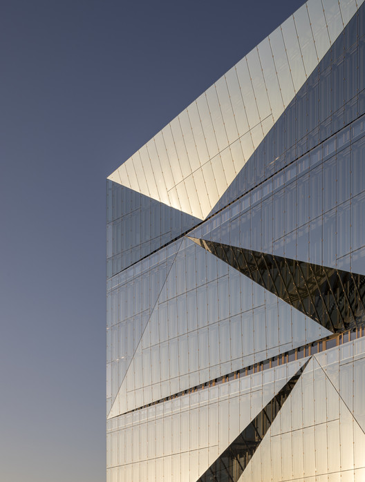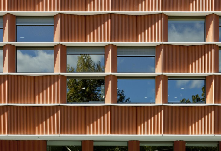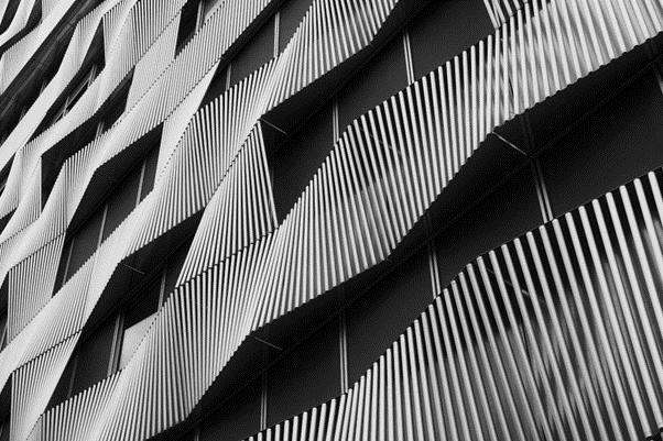
While cladding panels define a building’s aesthetic identity, the ultimate performance of a ventilated facade relies entirely on its unseen skeleton: the subframe system. Positioned between the structural backing wall and the exterior cladding, this engineered substructure distributes loads, compensates for construction tolerances, eliminates thermal bridging, and maintains the continuous air cavity essential for thermodynamic performance.
1. Wall Brackets: Managing Loads and Thermal Movement
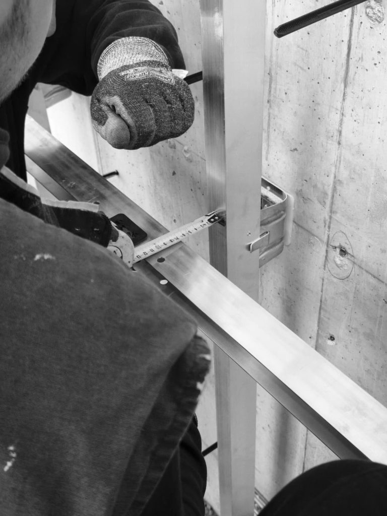
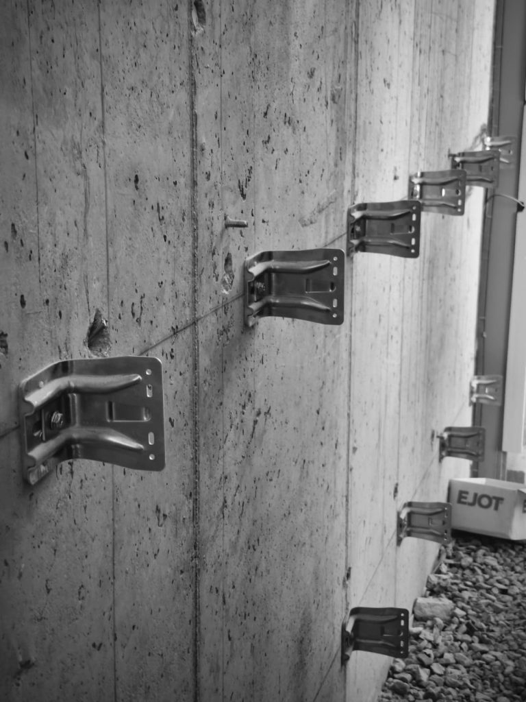
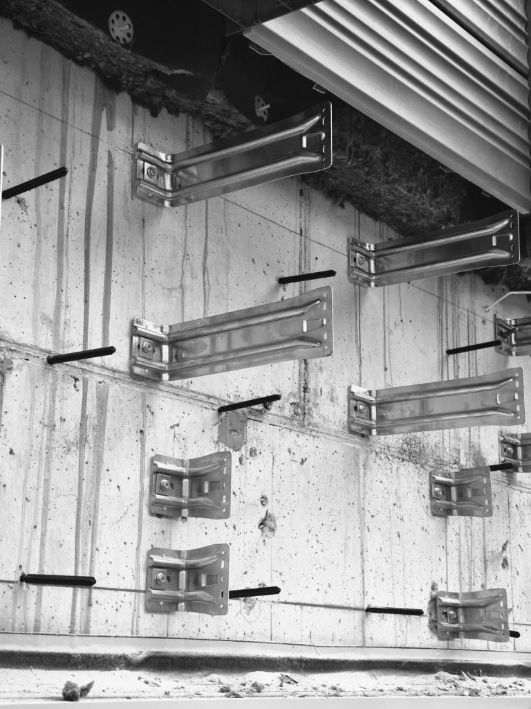
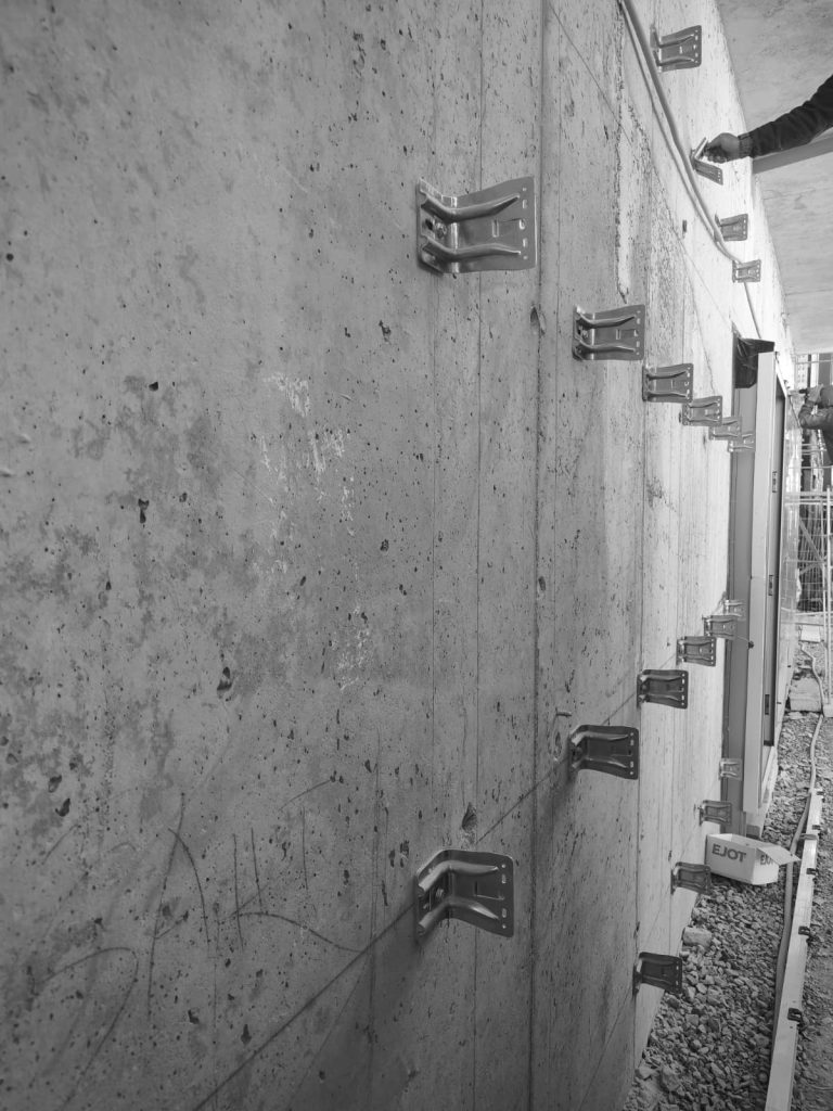
Brackets (wall mounts) serve as the primary structural anchors connecting the subframe to the building’s load-bearing substrate (concrete, masonry, or steel). To accommodate building movement and temperature fluctuations, brackets are strictly divided into two functional types:
- Fixed Brackets (Dead Load Points): These anchor points bear the full dead load (weight of the cladding panels and profiles) as well as wind pressure and suction. Profiles attach to fixed brackets through round holes, establishing a rigid zero-height benchmark for each vertical rail.
- Sliding Brackets (Expansion Points): These anchors carry only wind loads (positive pressure and negative suction) and bear no vertical weight. Profiles attach through elongated (oval) slots, allowing the metal profiles to slide vertically as they expand and contract under temperature changes. Without sliding points, thermal movement causes profile buckling, panel distortion, and fastener shearing.
- Thermal Isolation Pads: Mounted directly between the bracket base and the structural wall, these high-density polyamide or EPDM pads prevent point thermal bridging and eliminate galvanic corrosion caused by direct contact between dissimilar metals (such as aluminum brackets and steel rebar).
2. Profile Geometry: Vertical and Horizontal Grids
Extruded aluminum or steel profiles form the structural grid that supports the cladding panels while defining the depth of the ventilation cavity.
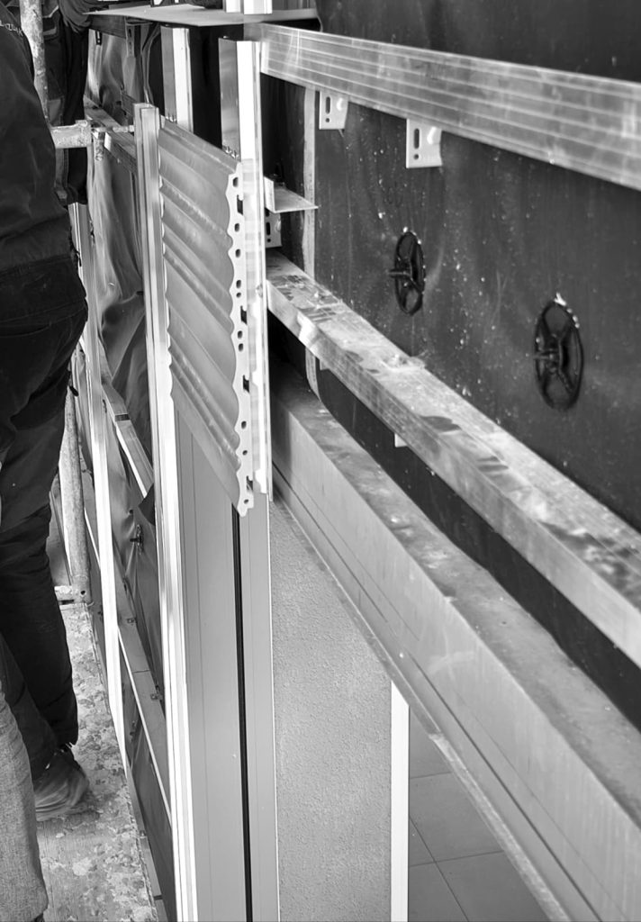
- Vertical T-Profiles: Installed at the vertical joints (fugas) between adjacent cladding panels. The wide flange of the T-profile provides an ample landing area to secure the edges of both panels while leaving a uniform expansion gap between them.
- Vertical L-Profiles: Positioned as intermediate supports along the mid-span of wider panels to prevent wind-induced deflection, as well as at internal and external building corners.
- Horizontal Profiles: Applied as a secondary sub-grid when cladding materials require horizontal hanging or hidden mechanical retention (such as terracotta tiles, grooved ceramic panels, or cassette systems). Horizontal profiles are always mounted over vertical profiles to ensure the primary vertical airflow in the cavity remains unblocked.
3. Engineering Rules for Thermal Expansion
Aluminum expands significantly under direct solar heating (approximately 1.2mm per meter over 50° C temperature differential). Preserving the integrity of the envelope requires strict adherence to structural detailing rules:
- The Single Fixed-Point Rule: Every individual vertical profile run must have only one set of fixed brackets (typically placed near the upper third or center of the profile length). All remaining brackets along that specific profile must be sliding brackets.
- Profile Expansion Joints: Vertical profiles are never installed as unbroken continuous rails up the full height of a building. Profiles are typically cut to floor-to-floor heights (approx. 2.80m to 3.60m) with a 10 mm to 15 mm expansion gap left between the ends of adjoining profiles.
4. Panel Attachment Methods
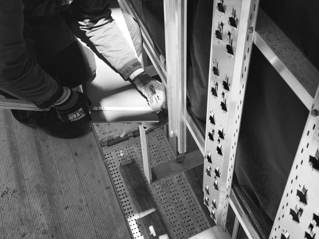
- Visible Mechanical Fixings: Panels attach directly to vertical T- and L-profiles using color-matched rivets or exposed screws with EPDM sealing washers.
- Concealed Mechanical Fixings (Agraffe Systems): Specialized undercut anchors (such as Keil or Fischer bolts) are drilled into the rear face of the cladding panels. Hooks (agraffes) mounted to these anchors hang onto horizontal profiles, allowing precise 3D leveling adjustment on site.
- Structural Bonding: Panels are attached to vertical profiles using structural polyurethane or hybrid adhesive tapes and pastes, offering a completely seamless exterior face free of visible mechanical hardware.
Subframe Component Overview
| Component | Primary Function | Key Technical Feature |
| Fixed Bracket | Bears dead load + wind loads | Round anchor holes; locks profile height position |
| Sliding Bracket | Bears wind loads only | Oval slots; permits axial thermal movement |
| Thermal Isolator Pad | Blocks thermal bridging & galvanic corrosion | High-density polyamide/EPDM insulating barrier |
| Vertical T-Profile | Supports panel joint edges | Wide flange for dual panel landing & cavity depth |
| Vertical L-Profile | Mid-span panel support & corner detailing | Prevents panel flexing under negative wind suction |
| Horizontal Profile | Secondary rail for concealed hanging systems | Used for terracotta, cassettes, and agraffe hooks |
Treating the subframe as a central element of the design process ensures that a ventilated facade achieves its intended design lifespan. Proper bracket distribution, thermal isolation, and expansion joints transform an ambitious exterior concept into an engineered, long-lasting building envelope.