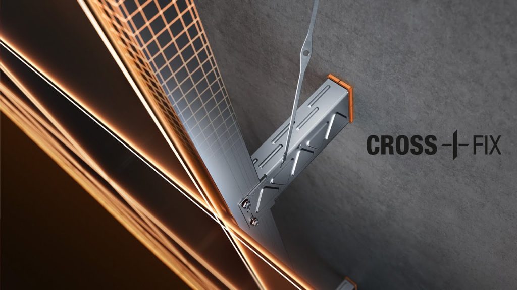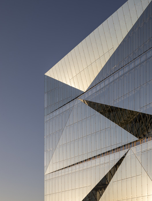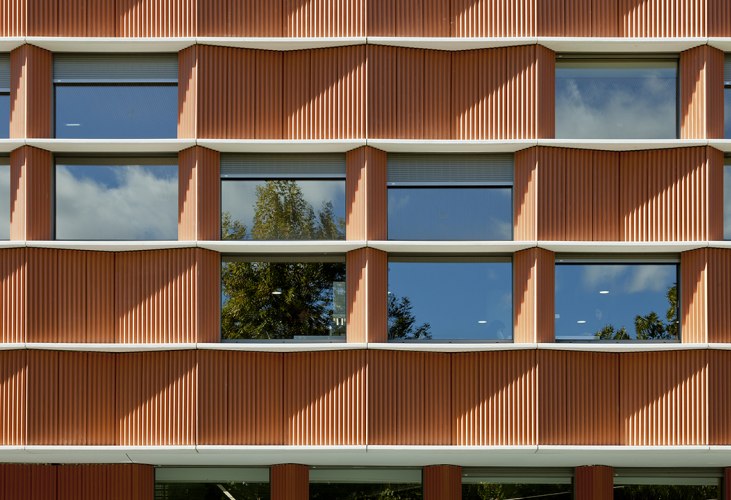
When specifying a ventilated facade (Rainscreen Cladding System), architectural discussions usually focus on the visual impact of the exterior cladding: the warm texture of terracotta, the sleek precision of fiber cement, or the sharp lines of metal cassettes. However, the long-term durability, safety, and pristine alignment of that exterior skin depend entirely on an unseen structural element behind it: the subframe bracket system.
For architects, understanding the distinction between fixed brackets and sliding brackets is not just an engineering detail—it is a fundamental requirement to prevent panel buckling, joint displacement, sheared fasteners, and structural fatigue over a building’s lifecycle.
Here is a comprehensive breakdown of how these brackets differ, why both are essential, and how they work together to manage structural loads and thermal movement.
The Fundamental Physics: Why Metal Subframes Move
Building envelopes are subject to intense environmental fluctuations. Aluminum—the primary material used for modern rainscreen subframes—has a high coefficient of thermal expansion.
To put this into perspective, a standard 3 meter vertical aluminum rail exposed to a seasonal temperature differential of 50°C (ranging from winter freezing to direct summer sun absorption) will expand and contract by approximately 3.5 to 4 millimeters.
If a rigid aluminum rail is anchored tightly to a concrete wall at multiple points without allowing for this movement, the thermal expansion forces become immense. Trapped kinetic energy will cause the profile to bow outward, stress the cladding anchors, shear off mechanical rivets, and ultimately distort or crack the exterior panels.
To solve this, facade engineering divides subframe wall mounts into two distinct functional types: Fixed Brackets and Sliding Brackets.
1. Fixed Brackets (Dead Load Points)
Fixed brackets act as the primary structural anchors of the facade profile. They establish the zero-height benchmark and carry the static weight of the system.
- Primary Function: They support the dead load (G)—the total vertical weight of the subframe profiles and the attached cladding panels—as well as dynamic wind loads (positive pressure and negative suction).
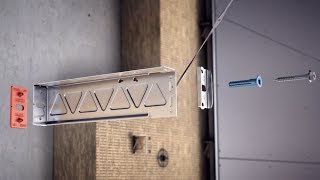
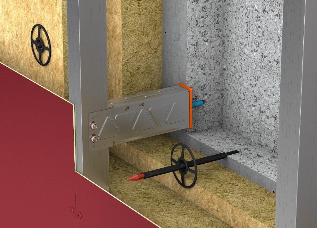
- Mechanical Connection: Fixed brackets feature precision round holes in their mounting face. The vertical aluminum profile is secured through these round holes using stainless steel or aluminum rivets/bolts. Because the holes match the fastener diameter, zero vertical movement is permitted at this connection.
- Placement Rule: Every individual vertical rail must have only one set of fixed brackets, typically positioned near the top third or center of the profile’s length. This single anchor point holds the profile in its exact vertical position relative to the building structure while allowing the rest of the rail to expand freely away from it.
2. Sliding Brackets (Expansion Points)
Sliding brackets (also known as flexible or floating points) provide lateral stability while accommodating thermal movement along the profile’s length.
- Primary Function: They carry only wind loads (positive wind pressure pushing against the facade and negative suction forces pulling away from it). They do not carry any vertical dead load weight.
- Mechanical Connection: Sliding brackets feature elongated (oval/slotted) holes along their vertical axis. Fasteners are placed through the center of these slots but are engineered to allow the profile to slide up and down freely inside the oval path as the metal expands or contracts.
- Placement Rule: All remaining brackets along a vertical profile rail—above and below the single fixed bracket—must be sliding brackets.
The Anatomy of the Bracket Connection
| Feature | Fixed Brackets (Dead Load Points) | Sliding Brackets (Expansion Points) |
| Supported Loads | Vertical Dead Load (G) + Horizontal Wind Loads (W) | Horizontal Wind Loads (W) only |
| Hole Geometry | Precision Round Holes | Elongated Oval / Slotted Holes |
| Profile Movement | Completely locked (zero vertical movement) | Guided axial movement (free sliding along slot) |
| Quantity Per Rail | Strictly 1 pair per vertical profile run | Multiple (spaced according to wind load engineering) |
| Primary Risk if Misspecified | System failure if multiple fixed points restrict expansion | Profile instability or sagging if fixed point is missing |
Critical Detailing Rules for Architectural Specifications
To ensure the subframe performs as intended over a 50+ year service life, architectural drawings and project specifications must incorporate these critical installation principles:
A. The “Single Fixed Point” Principle
A common installation error on site is fixing a vertical rail rigidly at both the top and bottom floor slabs. If a single aluminum profile is locked at two fixed points, it loses its ability to dilate. When heat builds up inside the air cavity, the profile will buckle outward, pushing the cladding panels out of alignment. Always specify that each profile run receives only one fixed point.
B. Profile Interruption at Floor Slabs (Dilatations)
Vertical profiles should never run continuously across the entire height of a building. Instead, profiles are typically manufactured in floor-to-floor lengths (approx. 2.80m to 3.60m). A net expansion gap of 10 mm to 15 mm must be left between the ends of adjoining vertical profiles. This gap ensures that as the lower profile expands upward and the upper profile expands downward, they do not collide.
C. Thermal Isolation Pads (Breaking the Thermal Bridge)
Because wall brackets penetrate the continuous exterior mineral wool insulation to anchor into the concrete or masonry wall, metal brackets act as point thermal bridges. Architectural specifications should always mandate high-density polyamide or EPDM thermal isolator pads placed between the bracket base and the structural wall. These pads drastically reduce thermal transmission (x-value) and prevent galvanic corrosion between dissimilar metals.
D. Fastener Torque & Hardware Selection
In sliding brackets, installers must use specialized shoulder rivets or bolts engineered for slotted holes. Over-tightening standard rivets can clamp the bracket face so tightly against the profile that friction prevents sliding, effectively converting a sliding bracket into an unintended fixed point.
Summary: Architectural Takeaways
By understanding the distinction between fixed and sliding brackets, architects can better evaluate facade subframe submittals, conduct more rigorous job-site inspections, and prevent costly post-occupancy defects:
- Fixed Brackets lock the vertical position and bear panel weight through round holes.
- Sliding Brackets stabilize against wind forces through oval slots, allowing the profile to breathe thermally.
- One Fixed Point Per Profile is the universal rule—never lock a single profile rail at multiple rigid points.
- Thermal Isolator Pads behind all bracket bases are essential for zero-emission envelope compliance.
Treating subframe detailing with the same rigor as exterior cladding selection ensures that your facade not only achieves its aesthetic vision on day one, but maintains its structural integrity, alignment, and thermal performance for decades to come.